Tuesday, 20 December 2016

Home Brewed Apple & Blackberry Wine

So.. Having successfully made rhubarb wine a few months back as can be seen here we decided to make some Apple and Blackberry wine. Here's how it went and how you can make your own.

Ingredients
----
Apples : 7.8kg
Granulated Sugar : 7.8kg
Black berries : 7.8kg
Lemons: 3
Yeast : 2 sachets
Yeast Nutrient : 5 tsp
Pectolase
--------------------------


********************
Lesson 1: You may get funny looks when buying all the ingredients
      ********************

Process
-       Chop the apples and black berries (blending the apples releases more juice) and throw these into a tub along with the sugar, 27L of boiled water, lemon juice and sugar.

-       Once the mixture is cool add the Pectolase. This will "reduce the risk of pectin hazes and also increases the yield from the juice pulp".

-       After 24 hours add the yeast and yeast nutrient.


********************
Lesson 2: Fermentation can get messy. Catch back blow with a glass.
      ********************

-       Leave for 1 week before checking that fermentation is complete using the hydrometer from the wine making kit purchased here.

-       Once Fermentation is complete you will want to transfer the wine to its new tub to get out all the berries and apple. This can be fairly tricky and messy. You will want to set some time aside for doing this and you will need to squeeze the apples and berries to get all the juice goodness out of them!


-       Leave the mixture for a month before repeating the procedure again, remembering to filter the fine as it comes through. Repeat this until the colouring looks as you'd like and/or your patience runs out. 

-       Clean your bottles and sterilise before bottling.


-       Give to family and friends.


Sunday, 11 December 2016

Building A Frog House - A Ribbiting tale

As autumn has moved towards us it is time to harvest the last allotment produce of the year and turnover the plot ready for a fresh year of growing. Whilst Louise and I were doing just this we decided to dig out the strawberry section we had, but in doing so - and so fervently - it ended with the heartbreaking murder of a little frog with my fork.

I found it all a bit sad so decided to giveback to the frog community by giving them somewhere they can live which is not between the vegetables.

I had a quick look online and it appears frogs like dark, damp places to hide over the winter. The obvious benefits being that they will eat the slugs and keep the population down. Having seen some examples I drew and showed Louise some options.
House 1: Plant Pot Vertical House 2: Wood Planks  House 3: Plant Pot Horizontal House 4: Stone, brick and logs
In the end I chose option 2 as we already had a bit of wood in the spare room. Some 2"x3" hardwood and plank like thin wood. I cut the wood into strips of 15cm. 4 of the 2x3 pieces per home and 3 plank pieces per home.


I then attached the 2"x3" pieces using a metal mending plate to hold them rigid together.

At the back, I screwed the plank piece at the back showing an even amount of space between top and bottom before tacking the remaining two pieces to the top. At this point it does not need to be even or smooth. Just roughly assembled.
 
At this point we could have left them as they were but Louise and I love a little competition so we decided to give them a paint and see whose was the best.

Louise's - Hop On Inn
Aiden's - Lily's Pad

Finally we put them out on the allotment with a hole at the centre and some dead leaves and grass for the frogs to hide in.

Now just to wait and see if we get any residents!


Monday, 28 November 2016

IBM MQ Exits - Good To Knows

I recently co-created a security and message exit. The main code was written in C for a linux machine. The exit was later needed for a windows machine. Here are some of the things I learnt when migrating from a linux exit to windows and reminders to myself for the future.

- Windows exits are compiled into dlls.

 - Whilst unix machines will allow you to compile C using gcc with declarations made at will throughout the code. It is integral that all these declaration are made at the start of each function for the windows platform.

- Another key thing learnt was that whilst in many examples you may see exporting functions in windows in the following form "__declspec( dllimport )" or by declaring "C extern". Being new to security exits on windows I hadn't realised that the external functions needed to be declared in a definition file or a .def in the following format.
"EXPORTS
ExitName"

- Exits names are case sensitive.

- Whilst Security Exits are needed both on the sender and receiver channels, message exits are only required on one of the channels.

It is highly recommended that anyone creating Exits have a knowledge of both MQ and the operating system/coding language being used and takes the time to understand the implications of the code being used and the security issues that may arise.

There is a useful resource on the IBM Knowledge centre for compiling exits which can be found here:
http://www.ibm.com/support/knowledgecenter/SSFKSJ_7.5.0/com.ibm.mq.dev.doc/q028160_.htm

Monday, 14 November 2016

Trello - Project Management & Collaboration

  Having in the past used various project management technologies for personal and professional projects I decided to have a quick look at ways Alastair and I and potentially anyone else who wants to join the robot car project can get involved interactively from different locations.

  In the past I had used Zenhub when playing around with code with an old university team. I decided to have another look at this tool for the robot car.

Zenhub Playing
    The first "issue" I had with this was that it was only available on firefox or chrome as an add on. Having just began life as a mac user I've been using safari more and more which has all my bookmarks, past site visits and is my current favourite browser to use.
 
   With Zenhub It is very easy to add "issues", assign people to these issues and then link these issues to code sources. This would be especially good since we will be sharing our Arduino code on github. Whilst looking at Zenhub i remembered having seen waffle in past and decided to have a look at that.
Waffle Playing
 Again this has a nice layout and is much easier to use than Zenhub. I personally believe that this integrates better and has better usability for adding comments and tagging other users.

These both work great for office based projects which you access daily on your laptop (albeit only on firefox or chrome). But for personal projects you want to be able to brainstorm throughout the day/week and this is best placed on an app as well as on the laptop.

I then started looking for project management apps. Most, such as Zoho and capterra were very bulky applications with Zoho having very comprehensive project capabilities - timeline, charts, costs etc application that would be going very over the top for what we needed.

Essentially we were looking for a simple system where I could add myself and Alastair and maybe two or three others if the "team" expands. What I eventually found was trello.

Easily adapted cards and labels
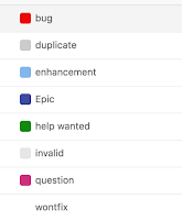
  Trello is extremely easy to use and has a lot of easy to use features such as; checklists on cards, checklist points can be made into individual cards, attachments can be easily added, users tagged in comments, deadlines set and labels can be customised a lot easier than the other sites mentioned.
Zenhub and Waffle labels are rightfully software project centric that are required more for teams to collaborate than individuals.
  What is also great is that its a mobile app that is more or less a to do list without needing a fridge whiteboard. The mobile app is "live" so when Louise and I created a "home" board and I went to do some last minute shopping she could easily update the shopping list as I walked around.


 With apps like these its little quirks that will draw a user in. I personally find this is the best for non work related projects that don't require lots of timeline and budgetary restraining and organising. It's easy to add comments, checklists and throw around ideas that would get lost in a whatsapp message/group.


Above you can see some more examples of tagging users to comments, labelling tasks and adding checklists.

I'm completely open to new ideas. so let me know if you use a different project management app? Do you agree/disagree with anything I've said?
I'd love to know your thought and/or what apps you and/or your teams use. Comment below if you have some insights. Thanks for reading

Friday, 11 November 2016

Robot Car V2.0

Robot Car V2.0


  A few weeks ago, we created the first version of our new and slowly improving robot car. For version 2 we added the front wheels, the body and a relay to control both sides from a single 9v battery.

  Continuining from the back of a "beer mat" design below we continued to implement.

Initial Design
Our parts list can be found here

  The first task to do was to re-cut and bend the wheel brackets, this aluminium was to be 11.5cm in length. The width was 2cm and each needed a hole drilling to allow the gears wheel connector to poke through and allow the wheel itself to sit on it.

  Once this was achieved we drilled out the rivets attaching the two wheels together from V1.0 and attached them to the larger frame using more rivets.

********************
Lesson 1: Make sure you have measured the rivet locations correctly or you will have wonky wheels
      ********************
   At this point we wanted to be able to thread the motor wires to the upper body to attach to the relay/battery etc. To do this we drilled two holes either side of the frame and attached grommets to them before threading through the motor wires - two to a side.

********************
Lesson 2: Loose wires on a flimsy motor will easily break. SECURE them
      ********************
  As can be seen in lesson 2. The wires being loose underneath the frame caused them to turn and pull whilst manoeuvring them. This lead to the wires coming off the motors and needing urgent soldering surgery. To secure them, we have now added cable ties that attach the wires tort at the base of the motor.

  Once the wires were threaded through we attached we placed the relay on the frame on top of a piece of cardboard to reduce the chances of the relay etc. shorting out.

Ready to wire
  For V2.0 we decided we would just directly connect the motors to the relays switches as well as the battery. The wiring system we chose can be seen in the image below. We are currently researching a system diagram creator (software). Any suggestions would be greatly appreciated!


Current confusing wiring diagram - wired connectors between NC and NO


  As you can see/not see in the diagram above, red wires show positive energy flow, black wired show ground and the blue wires are just connectors. The blue boxes are motors, yellow box is battery, the centre grey circle is a wire connector and the orange box is the relay module with the grey boxes inside being each switch.

  It's quite obvious that this form of drawing diagrams is going to be quickly untenable. But we live and learn.
Tidy and Smart wiring
  This wiring allows the robot to go in a straight line. With slight moving of wires you can make the car go in a circle but I'll leave you to play to make that happen. Below is a video of the robot in motion. We move onwards.
-----------------------------------------------
In Action:


Wednesday, 19 October 2016

Robot Car V1.0

Robot Car V1.0


A few months ago we created a cardboard framed "robot" that moved forward when three sensors on the front were covered. The wheels were made out of milk tops and chiseled wood. The batteries were so heavy we had to hold them behind the car as it drove.

It wasn't fit for purpose but was a great proof of concept. We decided to start creating the robot for real. I'm going to document in parts the progress we are making.

Initial Design
On the back of a "beer mat" we sketched our rough idea.

Parts To Buy

-------------------------
4 Arduino Smart Car Robot Plastic Tire Wheel with DC 3-6v Gear Motor - £5 to £8
Aluminium offcuts - £0 (up to £14)
Arduino Uno r3 - £2.40 to £8
2 9v Rechargable Batteries - £12 - £30
4 channel 5v relay module board - £1.83 to £6
6+ Photo resistors - £1.50 to £3
Various Jumper Wires - £2 to £4
----------------------
Total Cost: £24.73 to £73
----------------------

  Our first task was to create a prototype so we knew how to cut the offset of metal we had. The idea based on the above diagram was to have a flat piece of aluminium with a slight protrusion either end. The plan is for bi-directorional movement of the robot so it will eventually move in both directions with no clear "front".

Cardboard Prototype With Part Placement
  The prototype measured at 19cm x 9cm with the tops coming in by 1cm either side. We also measured some brackets that could be used to hold the motors and therefore the wheels in place.       
  These were 11.5cm in length. We then cut these out of the aluminium offcuts we had.


********************
Lesson 1: Don't do this in a shed on an allotment with no lights at 8pm in October
      ********************
********************
Lesson 2: If you need 4 equal length pieces... measure them correctly
      ********************

Having cut two of the metal pieces a little short we decided to make a smaller two wheeled car as it was too dark to cut more aluminium strips.

  The next step was to bend the metal strips that would hold the motors and to solder wire to the motors using red for positive charge and black for ground.


  Once the wheels were in place we secured them by drilling a hole where there was a small plastic dial on the gears plastic. This allowed the gear to sit comfortably. After riveting the holder together the gear was solidly in place and each of the two sides were connected to a long metal strip which connected them.
  At the centre of this we sellotaped one of the 9v batteries and connected wires from each of the two motors to the batteries positive and negative.


  Having both the positive wires from the motor go to the negative on the battery and vice-versa meant the affect was for the robot to spin around in a circle. However having the two motors positive and negative wired to opposing positions on the battery will have made it go straight.


  Just for good luck we added a tail to one of the sides. This stopped the motors wires from dragging on the floor. The video below shows it in action.
-----------------------------------------------
In Action:


Sunday, 16 October 2016

Genius Advanced Mega Pixel Camera - Revealed

  Whilst travelling and teaching in Chile, my friend Ben and I had lost our camera whilst in Santiago, so went the next day to Maipu to buy a new camera. We were on a money saving mission and I paid somewhere in the region of $10,000 - $20,000 (CLP). Which is about £12 - £22 on a Genius Advanced digital lens upto 12mega pixel camera. The camera was great for the time but soon fell out of my graces when we landed on home soil and it's low mega pixel and short battery life were outweighed by the quality and ease of just having an iPhone.

Having now been sat in a cupboard for the better half of three years it was decided that it'd be much better if taken apart to uncover the secrets within. Here is the journey.


Thus far, thus easy. The above photos show the front "shell" with all the information attached clipped to the camera. At the back two solitary wires connect to the "capture" button which allows us to take photos.

In the third photo you can see where the SD card inserts. Just in front of that (closer to the front of the photo) is where the lithium battery sits. The battery itself is 3.7v / 550mAh which I can use in the future if i can find a safe way to charge it.

A small weight has been added to make the camera seem more 'authentic'

Now, when the camera was whole, there was a small toggle you could press on the right hand side with a picture of hills and then one of a flower. It would appear these were to give a landscape and portrait effect to the images being taken, although in truth there was a very marginal difference between the images. left - portrait right - landscape

I'd originally thought this would be a digital alteration but was actually achieved mechanically using a push lever up or down. The affect of pushing the lever is changing the focus of the lens, though to two specific places so not very useful. 
 
The lever that changes the focus of the lens
At the back we can start to see the motherboard with its in-built controls that attach to the monitor. The monitor itself is a "2.7 inch 39 pin TXDT270CDR-8 LCD SCREEN Digital camera monitor" which hopefully can be used in later projects. The monitor simply unplugged from the motherboard and can easily be used again. Also to be seen is a small capacitor which we believe is used to store energy which eventually allows the "flash" which would make sense as I could never flash when on the last two bars of battery.
There was lots of salvageable parts including the little screws which will come in useful in the future.
One of the parts I was most fascinated with was the lens, which was just two moveable bits of metal attached to the glass to change the focus.

I couldn't get the glass itself out but overall it was fun to disassemble, though not designed to be taken apart so impossible to put back together again.

I'm looking forward to playing about with the monitor in the future - if anyone has instructions for these or know where I can find some it would be hugely appreciated.
All the bits in a single photo.