Showing posts with label arduino. Show all posts

Wednesday, 29 November 2017

Motion Detector using a PhotoResistor and Arduino

I recently brought two "WeMos D1 WiFi Uno ESP8266 ESP-12E Development Board" hoping to get my first connectivity of two arduino systems via wifi.

Getting the WeMos D1's working

The first task is to set up the arduinos. I could write out how in full, but there's no point in reinventing the wheel, especially when the instructables website does such a good job here:

Once we have this setup its important to understand how we get that connectivity to the internet, what code we need and what the errors and status codes we might see in order to handle them in the code. The best link I have found, or the simplest for Connecting Arduino to Wifi (including status codes) is the one below.

However, the easiest way to get something working straight away is to use: http://www.esp8266learning.com/wemos-webserver-example.php all that is needed is to set your wifi name and password, upload to your Arduino and your done. Follow the IP address that is printed on the serial monitor and you'll have a webpage where you can turn on and off the light of the arduino. 

Try it with any webpage viewable device connected to the same network and voila!

Do this with both Arduino's. One of the Arduino's will be used as a web server and the other will be used to send the sensor information to switch the light on, on the web server in order to "Alert" someone watching the server Arduino that someone has passed the sensor that could be in another room.

Setting up a sensor to output analog (Alert Arduino)

For this we will need;
 - 1 PhotoResistor
 - 3 Male to Male Jumper Cable
 - 1 Resistor
 - 1 Breadboard

We plug the PhotoResistor into the breadboard on one of the centre areas, one leg will be connected to a positive 5V charge from the Arduino. The other will have a resistor across it into a new line and also a male to male jumper cable into one of the analog pins. The final piece is to connect the other end of the resistor to GND (ground).
The sensor will be pointing off the table towards where you want to monitor
We need to add the variable for the photoResistor. 

Before the Setup Code we add:
int sensorPin = A0;    // select the input pin for the potentiometer
int sensorValue = 0;  // variable to store the value coming from the sensor
Within the loop:
sensorValue = analogRead(sensorPin);
Serial.println(sensorValue);

The information for this was taken from here: https://www.arduino.cc/en/Tutorial/AnalogInput
Once this runs we will start to see the unhindered sensor reading. In my case, this was around 355 - 380 and when covered by hand close and far the readings varied from 150 - 350. 

We can then add some code to the loop to turn the light on/off depending on the value returned by the sensor.
   if(sensorValue > 350){
      //turn light off
   }else{
      //turn light on
   }

Waiting for the Alert (Server Arduino)

We need to add the listener to turn on the light when the sensor is triggered.

In the "match request" section underneath the /LED we need to setup actions when the sensors alert.
  if (request.indexOf("/sensor=ON") != -1){
    digitalWrite(ledPin, HIGH);
    value = LOW;
  }
  if (request.indexOf("/sensor=OFF") != -1){
    digitalWrite(ledPin, LOW);
    value = LOW;
  }
Upload.

To test we can go to 
IPAddress:/sensor=ON
and then
 IPAddress:/sensor=OFF
on a network connected device. We should see the server Arduino's light turn on and then off. 

Posting an Alert when the sensor is triggered (Alert Arduino)

After a little google, the best Arduino POST example I could find using the examples we have was the answer by "stiff" on the following stack overflow question: https://stackoverflow.com/questions/3677400/making-a-http-post-request-using-arduino

Where we need to add;
   #include <ESP8266HTTPClient.h> 
   //inside the loop
   HTTPClient http;    //Declare object of class HTTPClient
   http.begin("http://IPAddress/sensor=OFF");      //Specify request destination
   http.addHeader("Content-Type", "text/plain");  //Specify content-type header
   int httpCode = http.POST("Message from ESP8266");   //Send the request
   String payload = http.getString();                  //Get the response payload

   Serial.println(httpCode);   //Print HTTP return code
   Serial.println(payload);    //Print request response payload
   http.end();  //Close connection
We can then use the:
 http.begin("http://IPAddress/sensor=ON");
with the sensorValue IF statement we made earlier.
if(sensorValue > 350){
   http.begin("http://IPAddress/sensor=OFF");      //Specify request destination
 }else{
   http.begin("http://IPAddress/sensor=ON");
  }
We have now completed the minimum viable product. I will share the full source code below as well as a video of the result. If you have any questions or would like the source code directly feel free to comment!
*UPDATE: below the original source code is an adapted piece of code which is much quicker and more responsive! enjoy!

Full Source Code: 

Alert Arduino: (With Sensor)

#include <ESP8266HTTPClient.h>
#include <ESP8266WiFi.h>

const char* ssid = "XXX";
const char* password = "YYY";

int ledPin = D5;
int sensorPin = A0;
int sensorValue = 0;

void setup() {

  Serial.begin(115200);                 //Serial connection
 
  // Connect to WiFi network
  Serial.println();
  Serial.println();
  Serial.print("Connecting to ");
  Serial.println(ssid);
  WiFi.begin(ssid, password);   //WiFi connection

  while (WiFi.status() != WL_CONNECTED) {
    delay(500);
    Serial.print(".");
  }
  Serial.println("");
  Serial.println("WiFi connected");

}

void loop() {
   sensorValue = analogRead(sensorPin);
   Serial.println(sensorValue);
   if(WiFi.status()== WL_CONNECTED){   //Check WiFi connection status

   HTTPClient http;    //Declare object of class HTTPClient
   if(sensorValue > 350){
   http.begin("http://
IPAddress/sensor=OFF");      //Specify request destination
   }else{
   http.begin("http://IPAddress/sensor=ON");
   }
   http.addHeader("Content-Type", "text/plain");  //Specify content-type header
   int httpCode = http.POST("Message from ESP8266");   //Send the request
   String payload = http.getString();                  //Get the response payload

   Serial.println(httpCode);   //Print HTTP return code
   Serial.println(payload);    //Print request response payload
   http.end();  //Close connection

 }else{

    Serial.println("Error in WiFi connection");

 }

  delay(10);

Server Arduino:

#include <ESP8266WiFi.h>

const char* ssid = "XXX";
const char* password = "YYY";

int ledPin = D5;
WiFiServer server(80);

void setup() {
  Serial.begin(115200);
  delay(10);


  pinMode(ledPin, OUTPUT);
  digitalWrite(ledPin, LOW);

  // Connect to WiFi network
  Serial.println();
  Serial.println();
  Serial.print("Connecting to ");
  Serial.println(ssid);

  WiFi.begin(ssid, password);

  while (WiFi.status() != WL_CONNECTED) {
    delay(500);
    Serial.print(".");
  }
  Serial.println("");
  Serial.println("WiFi connected");

  // Start the server
  server.begin();
  Serial.println("Server started");

  // Print the IP address
  Serial.print("Use this URL : ");
  Serial.print("http://");
  Serial.print(WiFi.localIP());
  Serial.println("/");

}

void loop() {
  // Check if a client has connected
  WiFiClient client = server.available();
  if (!client) {
    return;
  }

  // Wait until the client sends some data
  Serial.println("new client");
  while(!client.available()){
    delay(1);
  }

  // Read the first line of the request
  String request = client.readStringUntil('\r');
  Serial.println(request);
  client.flush();

  // Match the request

  int value = LOW;
  if (request.indexOf("/LED=ON") != -1) {
    digitalWrite(ledPin, HIGH);
    value = HIGH;
  }
  if (request.indexOf("/LED=OFF") != -1){
    digitalWrite(ledPin, LOW);
    value = LOW;
  }
  if (request.indexOf("/sensor=ON") != -1){
    digitalWrite(ledPin, HIGH);
    value = LOW;
  }
  if (request.indexOf("/sensor=OFF") != -1){
    digitalWrite(ledPin, LOW);
    value = LOW;
  }


  // Return the response
  client.println("HTTP/1.1 200 OK");
  client.println("Content-Type: text/html");
  client.println(""); //  do not forget this one
  client.println("<!DOCTYPE HTML>");
  client.println("<html>");

  client.print("Led pin is now: ");

  if(value == HIGH) {
    client.print("On");
  } else {
    client.print("Off");
  }
  client.println("<br><br>");
  client.println("Click <a href=\"/LED=ON\">here</a> turn the LED on pin 5 ON<br>");
  client.println("Click <a href=\"/LED=OFF\">here</a> turn the LED on pin 5 OFF<br>");
  client.println("</html>");

  delay(1);
  Serial.println("Client disconnected");
  Serial.println("");

}
Results:


UPDATE: From the above video we can see that the response is pretty slow with the code we have. To fix this I have edited the "Alert Arduino" code. Below is the results of changes made (below that will be the code).


Video Links: https://www.youtube.com/watch?v=Pfqs-WN9OiQ
                      https://www.youtube.com/watch?v=iTQJmba_wcw

Updated Code:

Alert Arduino: (With Sensor)
#include <ESP8266HTTPClient.h>
#include <ESP8266WiFi.h>

const char* ssid = "XXX";
const char* password = "YYY";

int ledPin = D5;
int sensorPin = A0;
int sensorValue = 0;
int sensorOn = 0;
int currentSensor = 0;

void setup() {

  Serial.begin(115200);                 //Serial connection
 
  // Connect to WiFi network
  Serial.println();
  Serial.println();
  Serial.print("Connecting to ");
  Serial.println(ssid);
  WiFi.begin(ssid, password);   //WiFi connection

  while (WiFi.status() != WL_CONNECTED) {
    delay(500);
    Serial.print(".");
  }
  Serial.println("");
  Serial.println("WiFi connected");

}

void loop() {
   sensorValue = analogRead(sensorPin);
   Serial.println(sensorValue);
   if(sensorValue > 350){
    sensorOn = 0;
   }else{
    sensorOn = 1;
   }
 
   if(WiFi.status()== WL_CONNECTED){   //Check WiFi connection status

   HTTPClient http;    //Declare object of class HTTPClient
 
   if(currentSensor == 1 && sensorOn == 0){
 
    currentSensor = 0;
    http.begin("http://IPAddress/sensor=OFF");      //Specify request destination
    http.addHeader("Content-Type", "text/plain");  //Specify content-type header
    int httpCode = http.POST("Message from ESP8266");   //Send the request
    http.end();  //Close connection
 
   }else if(currentSensor == 0 && sensorOn == 1){
 
    currentSensor = 1;
    http.begin("http://IPAddress/sensor=ON");
    http.addHeader("Content-Type", "text/plain");  //Specify content-type header
    int httpCode = http.POST("Message from ESP8266");   //Send the request
    http.end();  //Close connection
 
   }else{
 
    //do nothing
 
   }
   //String payload = http.getString();                  //Get the response payload
   //Serial.println(httpCode);   //Print HTTP return code
   //Serial.println(payload);    //Print request response payload

 }else{

    Serial.println("Error in WiFi connection");

 }

  delay(500);

}

Wednesday, 19 October 2016

Robot Car V1.0

Robot Car V1.0


A few months ago we created a cardboard framed "robot" that moved forward when three sensors on the front were covered. The wheels were made out of milk tops and chiseled wood. The batteries were so heavy we had to hold them behind the car as it drove.

It wasn't fit for purpose but was a great proof of concept. We decided to start creating the robot for real. I'm going to document in parts the progress we are making.

Initial Design
On the back of a "beer mat" we sketched our rough idea.

Parts To Buy

-------------------------
4 Arduino Smart Car Robot Plastic Tire Wheel with DC 3-6v Gear Motor - £5 to £8
Aluminium offcuts - £0 (up to £14)
Arduino Uno r3 - £2.40 to £8
2 9v Rechargable Batteries - £12 - £30
4 channel 5v relay module board - £1.83 to £6
6+ Photo resistors - £1.50 to £3
Various Jumper Wires - £2 to £4
----------------------
Total Cost: £24.73 to £73
----------------------

  Our first task was to create a prototype so we knew how to cut the offset of metal we had. The idea based on the above diagram was to have a flat piece of aluminium with a slight protrusion either end. The plan is for bi-directorional movement of the robot so it will eventually move in both directions with no clear "front".

Cardboard Prototype With Part Placement
  The prototype measured at 19cm x 9cm with the tops coming in by 1cm either side. We also measured some brackets that could be used to hold the motors and therefore the wheels in place.       
  These were 11.5cm in length. We then cut these out of the aluminium offcuts we had.


********************
Lesson 1: Don't do this in a shed on an allotment with no lights at 8pm in October
      ********************
********************
Lesson 2: If you need 4 equal length pieces... measure them correctly
      ********************

Having cut two of the metal pieces a little short we decided to make a smaller two wheeled car as it was too dark to cut more aluminium strips.

  The next step was to bend the metal strips that would hold the motors and to solder wire to the motors using red for positive charge and black for ground.


  Once the wheels were in place we secured them by drilling a hole where there was a small plastic dial on the gears plastic. This allowed the gear to sit comfortably. After riveting the holder together the gear was solidly in place and each of the two sides were connected to a long metal strip which connected them.
  At the centre of this we sellotaped one of the 9v batteries and connected wires from each of the two motors to the batteries positive and negative.


  Having both the positive wires from the motor go to the negative on the battery and vice-versa meant the affect was for the robot to spin around in a circle. However having the two motors positive and negative wired to opposing positions on the battery will have made it go straight.


  Just for good luck we added a tail to one of the sides. This stopped the motors wires from dragging on the floor. The video below shows it in action.
-----------------------------------------------
In Action:


Monday, 22 August 2016

An Arduino Powered Watering System

So it's finally been made.
In preparation for our trip to Italy, Louise's housemate Alastair and I have made an Arduino Powered Watering System.

The idea we formulated was to have a large water butt which lets water flow into a secondary container at set times. Once in the morning and once at night outside of the intense sun hours.
This secondary container will have water taps that are always on so water flows through. This was designed so we only have to power one servo to let all the water supply needed out in one go.

The list of things we needed and our estimate prices were;
----
rechargeable 12v battery lead acid - £8 - £20
Solar Charge Controller Panel Battery Regulator Safe 10A 12V/24V - £5 - £10
Tower Pro SG-90 SG90 9g Micro Servos  £2 -£4
Arduino Uno R3 - £5
25L - 45L tub - £7 - £25
long plant plot with flat sides - £3 - £10
air tight water taps - £3 - £4 each most retailers (5)
hose pipe - £5
Solar panel charger 10W 12V £15 - £40
2 Channel 5V High Level Trigger Relay Module - £1.50 - £5
Car wire Fuse - 15p
Dc Dc Step Down Converter Voltage Regulator 24v 12v To 5v Usb Charger Voltmeter - £1 - £3
------------------------------------------
In the end the total cost was: £80 (including broken parts) + £10 for a wooden frame
------------------------------------------
First we created a wooden stand to hold the 35L tub we had, hastily constructing it on the allotment using tools from the shed we'd inherited with the plot. We made sure there was just enough room for the secondary containers shelf so that the water was as high as possible. The higher the secondary container the easier water would flow into the pots using gravity alone.
The stand with two shelves


We then fitted the solar panel, a 12v 10w device that we connected to the roof of the greenhouse using bolts and a bit of wood. Making sure the solar panel faced south so as to get sun from morning to night. The solar panel hooked to the solar regulator which we attached to the left front stand so we could easily see the battery levels.
The regulator has three connection points; + and - for the solar panel, + and - for the battery and + and - for the thing being powered. In our case the Arduino. 


********************
Lesson 1: Just because an Arduino can take 12v input... it does't mean it should. 
hint - smoke and fire
********************
The servo - chosen after the terrible instrument called the solenoid, read more HERE - was attached to a water butt tap which it turns 75 degrees to an open position for x amount of seconds before closing. It then repeats the process having left enough time for some of the water to have got into the soil.


********************
Lesson 2: If you can't find the right resistor, do NOT connect a 12v power source to a 5v servo
********************

To make sure the servo isn't always on and therefore draining battery. The servo needed to have power to it stopped when not needed. To make this happen, the arduino was connected to the relays IN1 so that control of whether to power the servo could be decided by us. We then wired the servo to the IN1 relay output so it could be powered in these time.


Now. Lesson 1 taught us what havoc charging 12v to 5v device could cause, so we decided to obtain a 12v to 5v step down convertor, this would allow us to regulate the incoming power to the arduino and the servo whilst also reducing power usage.

 ********************
Lesson 3: Powering a step down convertor in reverse - 5v in the 12v ports and vice versa - results in ringing ears

********************

The next thing we added, to reduce the possibility of blowing everything up too often was the fuse, which meant the fuse would take the fall. Its actually had some value and we've only blown one up so far!

In all these fires and explosions, the only thing we haven't destroyed yet is the 12v car battery which has thus far served us well. This also connects to the solar regulator -  a very simple device that controls how much energy the Arduino receives, how much the battery takes and when to fill up the battery. 


The final pieces to discuss is the secondary tub. This is only suppose to fill up with just enough water to release into the taps connected to its sides. It does't need to be large as it should be dispensing water at the same rate it is receiving it. If it isn't then you are releasing too much water, either from the primary store or the taps aren't open enough.

**********************************

Below is a picture of the system drawn out:


**********************************

In Action:


If you would like to see the arduino source code, feel free to email me on aiden.g@live.co.uk


Saturday, 20 August 2016

The Snail Paced Drip Of The Solenoid

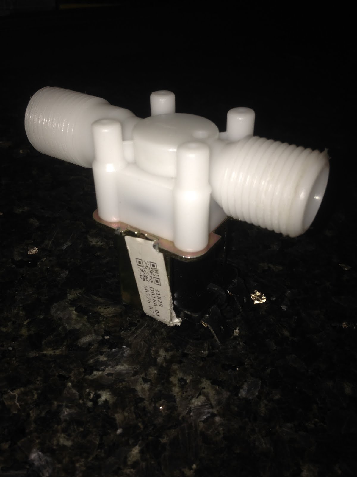
12v Magnetic Solenoid Valve
Whilst looking at options for making an Arduino powered watering system, I brought a “12v Electric Solenoid Valve Magnetic DC N/C Water Air Inlet Flow Switch ½”, attached it to a bucket of water and plugged it into a 12v battery. Immediately I heard a quick clocking noise as the magnet worked and water started flowing through. Slowly.

Very, very very slowly.

Drip, drip, drip. It became obvious that it would take a long time to water the greenhouse plants using this as we could be using anywhere up to 2 litres a day. This would drain energy the whole time it was activated. Whilst not a viable option for the project we decided to take it apart and find out how it works.

First came off the four screws at the top and then the white plastic that looked like a spinning top. Inside the long pole was a spring and a metal piece known as an “armature”. When current is passed into the solenoid, the core works to close the air gap between itself and the armature pulling it towards itself. This leaves a small opening at the “tap” allowing water to pass through. It would appear to be heavily reliant on pressure as added pressure made the flow marginally quicker but this was limited by the spring which is used to push the armature back in place post energizing.


Potentially what we could have done is cut some of the spring to allow more pressure when the magnet is activated, drawing the armature closer in. Again this change would be marginal whilst risking the possibility of not being able to seal the water gap when power is no longer supplied.


It would appear a servo would be the next thing to look at.

Wednesday, 10 August 2016

Watering your plants whilst on holiday.

My girlfriend and I have an allotment. We also enjoy going away for periods of time to see family and friends, or to go and see a bit of the world. Which is fine in rainy Britain for my outdoor plants, but less forgiving for my green house plants which can range from tomatos, to seedling carrots, to strawberry plants and herbs.

So what to do when we go away? We COULD pester our friends and flat mates but we can’t expect them to check up on our plants all the time. As I probably wouldn’t want to do it for other people.

This is a short blog about some of the options available to me. Based on the following requirements:
·      Needs to be able to water for around 7 days
·      Needs to provide the right amount of water for the plant it's serving
·      Needs to be able to service seed(ling)s
·      Accounts for different sized pots

Option 1: Upside Down Bottle
The classic upside down bottle in the soil. This consists of putting a hole or slightly opening a bottle lid, turning it upside down, cutting off the bottom and filling with water. This slowly releases water into the pot for the eager plant.
Benefits: Quick, effective, simple to make, simple to use.
Limitations: Need to buy many to deal with demand, hard to regulate water flow and maintain water amounts, needs bigger bottles for bigger plants which takes up room and is ugly.

Option 2: Mighty Dripper Ultimate Plant Watering Kit
You can find this product here
Similar system which allows for more pots to be watered from the same source. This hangs off a hook and drip feeds water all day to your plants.
Benefits: Cheap (£17), scalable for water output, can give more or less water to different plants
Limitations: Limited to 10.5L so limited number of days it can be used before refill.


2. http://www.verticalveg.org.uk/how-to-make-a-genuinely-self-watering-growing-system/
Link 2 is a very impressive way of watering your plants, and given time and resources infinite, it would be my preferred choice of watering.
Benefits: Allows plants to take what water they need, self-maintaining, no need for pots, can water the garden for a long time
Limitations:
Requires a lot of space, can be difficult to create and maintain, expensive.


Option 4: An Arduino controlled watering system

https://www.youtube.com/watch?v=oOmF2KA9Z0w
An Arduino controlled system would be able to water plants at a specific time, using mathematics to work out how much water a plant needs, based on the type of plant, size of the pot and the current temperature/soil dampness.
Benefits: Scalable, easy to code (if you know how), can be supplied by any water supply, parts are cheap (Arduino costs around £5), can be hidden away
Limitations: Needs a battery (potentially dangerous in a home), hard to code(if you don’t know how), hard to build, can be expensive if you need to buy lots of parts.


This concludes an overview of the options I saw. There were some variations but all used similar techniques which gave it the same benefits and limitations.

Any hints or tips on what I should do? Have you made your own watering System? Let me know in the comments.